Going to Great Lengths

One of the biggest challenges for businesses implementing a converged cabling infrastructure is the need to connect remote devices to the network. Zoran Borcic, Datacom product manager at cabling and systems specialist Draka, outlines the latest developments in long reach twisted pair copper cabling.

IP is being used for an increasing number of applications. Data, voice, security and building automation and management systems can now all run over a common twisted pair cabling infrastructure. More recently IP is being used for industrial applications, where the focus is on monitoring, control and data collection and visualisation – so called Supervisory Control and Data Acquisition or SCADA applications.

This shift to a converged cabling infrastructure is rapidly increasing as more and more business applications running on IP networks are introduced and increasing numbers of companies are recognising the potential value a converged cable network can bring. It is a shift that will place significant new demands on network infrastructure.

Multimedia networking is another growing trend, particularly in hotels, airports lounges and passenger ships, with applications ranging from distance learning to desktop video conferencing, instant messaging, workgroup collaboration, multimedia kiosks, entertainment and imaging.

In offices WLAN, and Wifi are gaining ground. In practice WLAN is integrated into cabling structures in line with EN50173. With the new generation WLAN 802.11ac we have the first volume application for 10GBase-T in offices, which requires dense 10Gb/s network of Class EA or better preferably with Power over Ethernet plus (PoE+) compatibility with Next Gen PoE.

first

The advantage of running all of these different applications over the same cabling infrastructure eliminates the need to design and install separate networks. It also simplifies network management including initial deployment and eventual reconfiguration; improves network scalability to accommodate growth; improves reliability, and offers considerable cost savings.

The disadvantage of converged cabling is that downtime no longer means employees just lose access to emails. Instead security, building management systems and video conferencing and power to remote devices will all be affected, which is why it is important to install only the best performing cables and connectivity components including jacks and patch panels.

These trends have all been taken into account by CENELEC in the new edition of EN 50173 Information Technology: Generic Cabling Systems. This is now divided into six categories:

EN 50173-1: General requirements

EN 50173-2: Office buildings

EN 50173-3: Industrial areas

EN 50173-4: Home environments

EN 50173-5: Data centres

EN 50173-6: Distributed building services

The way that the standard has been put together means that if a designer or specifier is looking to define the design for structured cabling in offices, then all they need to do is to simply refer to EN 50173-2: for industrial areas it is EN 50173-3. All of the application specific standards are underpinned by EN 50173-1: General requirements, which contains a lot of the detailed and technical information common to premises.

pic 2

One of the challenges of a implementing a converged cabling infrastructure is the need to reach remote IP devices, such as remote security cameras, external temperature sensors or external door locks to the network. With conventional twisted pair cabling the horizontal distance is limited to 100m from the panel to the device so the designers and installers generally have three options:

1. Use fibre optic cabling and an Ethernet media converter at both ends of the cable. Depending on the type of fibre and application, data transmission can be supported for distances in excess of 100m. While this solution is standard compliant, it can be expensive and critically it is not possible to power a device remotely using fibre.

2. Use XR transceivers is another solution for fibre optic systems. However, for xBase-T they are not available or applicable. They are also expensive.

3. Long reach copper cabling systems would appear to be the optimal solution because copper cabling is a convenient and cost effective solution, which enables power to be cost-effectively provided to a device via PoE. And, by avoiding the need for sub-distributors and media converters, this solution also has the advantage of reducing the amount of technical space needed for converged cabling.

Long reach copper cables

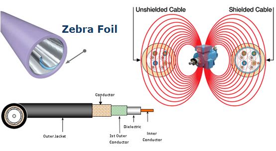
Cable and systems specialist Draka has introduced UC LR22 10Gbit U/FTP, a new compact cable which will help designers and installers power remote devices with ease. The shielded twisted pair cable is constructed from American Wire Gauge 22 copper core. It has an outside diameter of 8.2mm and is fabricated from low smoke halogen free (LSHF) materials and it has been optimised for PoE+/next gen PoE.

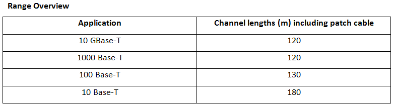
It meets all the requirements of the Ethernet standard IEEE 802.3 and ISO/IEC 11801 standards for 10GBase-T, PoE, PoE+ and a Class EA channel up to a length of 120m providing it has been installed with UC-Connect components and patch cables.

This unique cable allows the installed cable length to be longer while using the same installation practices as standard cabling solutions for peace of mind for installers and specifiers.

Because many applications supported by this extended cable are located outdoors, such as IP cameras, access controls and alike, the cable is also available in an outdoor version too.

pic 3

Standard compliant solution

In the first edition of ISO/IEC11801 a larger planning reach for services in Classes A, B or C has been part of the cabling scheme. Its logic was based on the fact a higher performing cabling can run longer distances with less demanding applications. This appeared to be forgotten in later editions of the cabling standard, although it still holds true. And, with applications located on the perimeter of LAN coverage, this fact regains importance.

Since length is only an informative measurement value and not a pass or fail criteria, testing an installed link is easy. Meters always show ‘Pass’ or ‘I’ (Only Informative Value) whatever the length. Within the ISO/IEC and CENLEC standards there is no length restriction for the transmission classes. What really matters is the end-to-end performance of the link and the LR-cable ensures increased compliance thanks to its better reach capabilities.

Since some BMS devices run at limited data rates of 100Mb/s or even less, the LR cable offers even larger link extensions. Autonegotiation of speed levels, in which two connected Ethernet devices choose the highest transmission mode they both support, makes administration easy and allows runs to remote devices at distances up to 180m.

The LR cabling approach is fully standard compliant. It enables the cost-efficient use of existing LAN infrastructure for increasingly important building management systems. It can easily be embedded in existing LAN cabling systems where it works as well as installing a new installation from scratch.

table

Zoran Borcic, is Product Manager Datacom Cable.
He looks after the global Draka branded Datacom copper cable portfolio of Prysmian Group’s Multimedia Solutions business unit. Zoran has experience in business administration, sales and product management in telecommunications and electronics industries. His responsibility within Draka is centred on product management and global coordination with local sales organizations.


Source: Technical MMS UK

BendBrightXS Fibre Recognised by Frost & Sulivan

Prysmian Group was awarded the 2015 European New Product Innovation Award for its BendBrightXS optical fibre by Frost & Sullivan, the world leader in growth consulting and the integrated areas of technology research and market research.

Every year in London, it presents this award to the company that has developed an innovative product by leveraging leading-edge technologies.

The award recognizes the value-added features and benefits of the product and the increased ROI it offers to customers, which in turn enhances end-customer acquisition and overall market penetration potential. BendBrightXS fibre, initially deployed for FTTH deployment, has now opened an innovative stairway for many new cable solutions applicable to a variety of network configurations.

It combines an unprecedentedly low macro-bending sensitivity (G.657.A2 compliant) and industry reference micro-bending performance, while still preserving all the features of regular singlemode fibre (G.657.D compliant).


Source: INSIGHT – Prysmian Group Quarterly Magazine, 03, 2015

Draka UC launches successfully in CommunicAsia 2015, attracting regional partners to our booth

Draka UC launches successfully in CommunicAsia 2015, attracting regional partners to our booth that showcased
Prysmian Group latest structured cabling portfolio and wide arrays of Multimedia Solutions cabling products.

For almost 10 years, Prysmian Group has actively participated in this event, reinforcing our reputation and status
as the World’s biggest and most active cable brand.

The highlights of this exhibition was the launch of the Gen2 end to end full solutions which places Draka brand in
the global giants of structured cabling. Prysmian Group also launches the pioneering technology for Category 8
cables as well as several innovation technologies.

Crowds were drawn to the innovations we had to offer and as a result several partnerships were inked in this
fruitful event.


Source:Marketing MMS Asia/em>

Draka UC joins Industry Certification Initiative in UK

Market-leading cable manufacturer Draka is the latest to have signed up to support the new Certified Network Cable Installer (CNCI) certification for cable installers. Draka will now accept this accreditation as a demonstration of competence for contractors looking to join its coveted UC Connect Approved Installers scheme. Product Manager for UC Connect, Lee Stokes, is hugely supportive of the new certification: “There is no doubt that this is a sign that the industry is at last growing up” he summarises. “For a long time the industry has needed a set level of competence that everyone recognises and trusts. The determination of the team at CNet Training has resulted in the CNCI programme to deliver that.”

For those who have yet to undertake CNCI programme, or who choose not to do so, Draka will still provide its current training programme to ensure all contractors have the opportunity to join the UC Connect scheme. However, CNet Training – providers of the CNIC programme – point out that the days of manufacturer-led training programmes may be numbered.

“The industry has been crying out for this type of universal certification for years yet nobody has been able to tackle the problem successfully” says CNet Training Managing Director Andrew Stevens. “Not only have installers and manufacturers been very quick to come on board but we are now starting to see the first specifications requiring the use of CNCI certified contractors. “

Lee Stokes sees benefits to both the manufacturer and installer: “Draka is a manufacturer not a training provider. Having an industry-led training programme delivered by a professional training company allows us to focus our resources where they should be – on providing the best products and most comprehensive technical support to our UC Connect installers.”


Source: Technical MMS UK

Application of Draka UC in Data Centre Cabling

Every data centre is a unique structure. There are various segments of different requirements which need to be understood before creating any solution.

In highly concentrated data centre networks, at server level (Client), they key is to maximize utilization of available pathways, racks and spaces rather than to go for maximum permissible channel length. The required channels of 20m to 60m average distances give room for optimized designs in cable. For this application Draka has developed the new UCFUTURE program which contains slim cable designs based on existing work area cable standards, which are perfect for zone cabling in data centres because of these characteristics.

Up to 100% higher packing density in cable trays

Fully compliant with established cable standards

PIMF design to eliminate any Alien-Xtalk interferences

Full 10GBase-T performance over a channel distance of 70m

Especially at Client level bulky cabling dorms a serious barrier to air ventilation, literally one of the hot topics in data centres due to growing packing density in server racks and the need to offload the high amount of heat dissipated by all the electronics. Slim designs at server level like the blade technology should be consequently transferred to slim cabling.

The advantages of the new cable design can be leveraged to most suitable slim-design connectivity products which give new opportunities for extended customer specific service concepts. Minimum required transmission performance of cable and cabling is Cat 6A and/or Class EA. The rationale is to ensure easy migration of services to 10GBase-T, for which cable standards based on various technologies were made.


Source: Draka UC Data Cable Brochure

Draka reinforces its position as a leading cable brand in Shielding Properties

  • Our leading technology in providing excellent shielding properties to our cables makes our cables highly resistance to even extensive Electromagnetic Interferences.
  • Unique patented 2 pairs foil (Zebra) for our Category Cables.
  • 95% shielding for our premium coaxial cables.
  • High shield protection for our data control cables, i.e. UL 2464 / EIA 485 / UL 2919 etc
  • Grade A copper and aluminum shielding materials used with unique wrapping methods.


Source: Technical MMS Asia

Draka UC showcased in UK Number 1 Network Infrastructure Magazine – June 2015

Multi-talented

Singlemode fibre optic cable is more and more considered as a viable solution for 10Gb/s LAN and data centre applications on the basis of price. Carsten Fehr at Draka/Prysmian Group argues that, despite the increased cable cost, multimode fibre is often the most economical solution.

The need and desire for more bandwidth and faster communication is rapidly growing across all types of communication networks. To support these demands in Ethernet networks, such as data centres, the IEEE developed and ratified the standard IEEE802.3ba in June 2010. This extends Ethernet speeds from 10Gb/s to 40Gb/s and 100Gb/s across single or multimode fibre optics.

Standard practice

The IEEE standard sets different link lengths for singlemode and multimode fibres. Multimode optical fibre will support both 40 and 100Gb/s speeds over lengths of at least 150m. Singlemode fibre will support 100Gb/s link lengths of 10 and 40km and a 40Gb/s link length of up to 10km. To supporters of twin fibre technology, even if the potential link distance of 10km is not required, using two singlemode 40GBase-LR4 fibres to create a network may appear to be a viable solution. However, today’s network manager must not only plan to upgrade to a 40 Gigabit Ethernet environment, they must also understand the implications that transformation will have on the eventual network migration to 100 Gigabit Ethernet and beyond. Whether a singlemode solution is the best option under these circumstances is questionable as the following examination of systems costs shows.

Two types

Light signals are typically transmitted along a fibre with a silica glass core that confines the incident light beam to the inside through total internal reflection.

Attenuation is an important factor limiting the transmission of a digital signal across large distances. When the first fibre optic fibre appeared in 1970, its optical attenuation (reduction in the intensity of the light beam with respect to distance travelled) was 20dB/km, which is far beyond the level of attenuation of today’s fibres.

The effects that contribute to attenuation depend on the optical wavelength of the transmitted signal. The wavelength bands, or windows, that exist where these effects are weakest are most favourable for transmission. It was the optical resonance of the hydroxide molecules in the glass, in particular, that made the wavelength window of 850nm favourable and earned it the moniker the ‘first optical window’.

As manufacturing technology advanced, process improvements then opened up further windows, of which the ‘second optical window’ of 1,310nm has become the most significant.

When manufacturers implemented the first commercial fibre optic transmission paths in the 1980s, there were two main problems: the coupling of sufficient light into the optical fibre; and the limitation of bandwidth due to dispersion, which is the spreading of the optical pulses as they travel along the fibre.

Increasing the size of the fibre’s light guiding core considerably simplifies the light coupling and cabling technology by transmitting light in a number of wavelengths (modes). These wavelengths, however, move at different speeds along the fibre distorting the signal. A graded index fibre core can be used to overcome this modal dispersion. This works by radially varying the refractive index of the core to even out the speed of travel of the different modes. However, its synchronising effect is limited.

A further reduction in dispersion is only possible by restricting operation to a singlemode, which requires very small core dimensions, less than 10μm, which in turn makes light coupling difficult.

The result of this dichotomy is that two distinct types of optical fibres have evolved. Singlemode fibres, with their smaller core, have come to dominate long distance applications, while the larger cored multimode fibres are more beneficial over shorter distances. As a consequence, multimode fibre is commonly used for inter- or intrabuilding applications while singlemode fibres are commonly used for communication links over 1km, for example for running a telecoms cable from one continent to another.

Historically, singlemode fibres transmitted infrared laser light, and multimode fibres transmitted infrared light from light emitting diodes (LEDs), which kept system costs low. Today, LEDs have been largely superseded by vertical cavity surface emitting lasers (VCSELs) which couple well to multimode fibre and offer improved speed, power and spectral properties, at a similar cost.

This divergence between single and multimode fibres was sanctioned with the introduction of multimode OM3 fibre, which was specifically optimised for VCSEL operation in the 850nm window. The deployment of 850nm fibre systems represents a significant saving over singlemode fibres for 10 Gigabit Ethernet users. So much so, that the cost of a singlemode link, including the transceiver either side of the fibre optic, soon exceeded that of the multimode option by a three digit Sterling sum.

Costs at a system level

Today, users have a multitude of fibre optic network options from which to choose. Compatibility is essentially guaranteed by standardised transceivers, which comply fully with physical medium dependent sub-layers (PMDs), which define the details of transmission and reception of individual bits on a physical medium. These ‘plug and play’ solutions allow the most economical transceiver for a transmission distance and speed to be selected.

There is no need to carry out a major cost analysis for proof of the price differential; the prices of cabling and transceivers are readily available on the Internet. A quick Google search of prices will show that the cost of a transceiver jumps considerably in line with the range of the PMD standard for any system supplier.

No matter which system brand you chose, the result will always be the same:

  • The lower priced singlemode fibre requires more expensive components than the more expensively priced multimode fibre.
  • Singlemode transceivers (10GBase-SR) cost between 25 and 130 per cent more than multimode transceivers at the same data rate.
  • The price differential of two such transceivers is at least €600, which makes it five times more expensive than the fibre optic cable linking them.
  • The subtotals of cabling, components and installation are always less than 10 per cent of the cost of the entire transmission path including the transceiver.

The difference in costs for active multimode and singlemode components, such as transceivers, becomes even more significant on large installations such as a data centre with, perhaps, 10,000 cable links. Here, even a small saving in component cost can result in a significant overall saving.

Longevity

To futureproof an installation to ensure its long term operation installers should consider using a solution which supports system upgrades and ever quicker transceivers in the most flexible manner. It should also be backwards compatible to allow the new systems to continue to operate with the existing system otherwise it is not possible to upgrade individual sections of the system without the entire active network having to be revised. This is the case for all users with 1GBase-SX and 100Base-SX systems in their network, neither of which is capable of operating on singlemode fibre.

The examples above demonstrate that if the cost of the network is important, there is no alternative to multimode fibre for LAN and data centre backbones. True, the range of multimode optical fibres will certainly shrink with higher data rates; as a result, the only solution for long range cabling will remain the singlemode fibre. However, to use this as a reason to fit out an entire optical fibre network would be an expensive mistake.

Future network 

expansion

Some users are already planning for 40 Gigabit Ethernet and beyond. The majority of these applications are switch-to-switch backbone installations comprising OM3 cabling with two fibres per section. The introduction of 40 Gigabit Ethernet does not give such backbones higher data densities since they continue to run 10Gb/s on two fibres.

In this instance the existing infrastructure can still be used by recabling. However, the amount of subsequent cabling of at least OM4 quality required is immense. The solution also costs roughly the same as the passive expansion with singlemode optical fibre but offers another upgrade option: 100GBase-SR4 with 4x25Gb/s on eight multimode optical fibres, which is in line with the advice in IEEE 802.3.

Once installed it is actually possible to enhance a system by upgrading the transceiver to 100 Gigabit Ethernet. At this network level, OM4 can be recommended as a flexible and reasonably priced cabling solution. As part of an independently planned cabling strategy, OM4 offers the option of reducing, and thereby simplifying the cabling runs without compromising the universality of the network.

With the next generation of networks moving towards 100 Gigabit Ethernet, new multimode fibre assessment criteria are emerging. Today’s 10Gb per fibre pair technology focuses on the effective modal bandwidth (EMB), which is determined by the differential mode delay (DMD).

For a standard OM4 fibre, a higher EMB would improve the workable fibre distance. This benefit is restricted to VCSELs with small to moderate spectral widths. For laser transceivers with increased spectral widths found on next generation networks, chromatic dispersion is responsible for restricting transmission lengths. The chromatic dispersion of the multimode optical fibres therefore takes on new significance.

In contrast to previous assumptions, the ideal DMD profile of a multimode optical fibre for use with VCSELs should not have perfectly synchronised modes. Instead it should deliberately aim to introduce modal dispersion to the signal to compensate for the chromatic dispersion. Such an OM4+ fibre is commercially available and can achieve ranges of up to 200m at 40/100 Gigabit Ethernet with selected transceivers as part of an engineered solution.


Source: NCN Magazine, UK

UCCONNECT® System Warranty

Draka UCCONNECT® 25 Years System Warranty covers our connectivity products and cable which ensures performance of the Permanent Link & Channel performance in accordance with ANSI/TIA/EIA-568-C and ISO/IEC 11801.

Getting the Certified System Installer status

Any installer that wishes to install Draka UC Structure Cabling Systems and wishes to apply
for the 25 years system warranty must complete a curriculum of Certified System Installer training.

Getting the Professional System Installer status

All completed Draka UC Structure Cablings Systems by an Professional System Installer shall be given an additional 3 years system warranty (Total 28 years) in recognition and fully confident of the integrity of their accomplished system.

For more information, email:mms.asia@prysmiangroup.com


Source: Technical MMS Asia

Importance of Reliability and Noise Immunity for Category Cables

RELIABILITY AND NOISE IMMUNITY

For many years, electromagnetic compatibility (EMC) has been a must for electric equipment.

The main problem is external interferences im­pacting the system and causing failures. In the network environment, there are various potential high-frequency interference sources that are between 80.0 MHz and 2.0 GHz, e.g. mobile radio, stationary radio and broadcasting stations, walkie-talkies and industrial RF sources. An IT system is being disrupted if a source generates an interfering pulse exceeding the limit/immu­nity of the receiving equipment. Further typical external interference sources are e.g. power cables and the switching-on of florescent lamps.


With high-quality cabling, a new problem arises: the Alien Crosstalk (between cables adjacent to each other).

Screening:

the basics

EMC defines the capability of a system to work without having a negative influence (emission of interference) on other systems.


Mostly, EMC interferences are electrically asymmetrical. That means, an interference source generates an interference that is in phase on both the neutral and live conductors with respect to earth. Regardless of the cause of interference, a symmetrical (balanced) cabling can minimize the interference when the two conductors of the symmetrical transmission channel are influenced in phase, as this is neglected.

Screening designs

Complying with the respective EMC requirements, our screened UC cables are available in the following designs:

/ S (Screen): Overall screen of aluminium-laminated foil / HS (High Screen): Screened with aluminium-laminated foil and tinned copper braid

/ SS (Super Screen): Pair screen with aluminium-laminated foil and overall screen with tinned copper braid.

The application of highly screened cables saves modifications when installations are expanded. For you, this means a very cost effective cabling solution for now and the future.


Source: Draka UC Data Cable Brochure