Draka UC showcased in UK Number 1 Network Infrastructure Magazine – June 2015

Multi-talented
Singlemode fibre optic cable is more and more considered as a viable solution for 10Gb/s LAN and data centre applications on the basis of price. Carsten Fehr at Draka/Prysmian Group argues that, despite the increased cable cost, multimode fibre is often the most economical solution.
The need and desire for more bandwidth and faster communication is rapidly growing across all types of communication networks. To support these demands in Ethernet networks, such as data centres, the IEEE developed and ratified the standard IEEE802.3ba in June 2010. This extends Ethernet speeds from 10Gb/s to 40Gb/s and 100Gb/s across single or multimode fibre optics.
Standard practice
The IEEE standard sets different link lengths for singlemode and multimode fibres. Multimode optical fibre will support both 40 and 100Gb/s speeds over lengths of at least 150m. Singlemode fibre will support 100Gb/s link lengths of 10 and 40km and a 40Gb/s link length of up to 10km. To supporters of twin fibre technology, even if the potential link distance of 10km is not required, using two singlemode 40GBase-LR4 fibres to create a network may appear to be a viable solution. However, today’s network manager must not only plan to upgrade to a 40 Gigabit Ethernet environment, they must also understand the implications that transformation will have on the eventual network migration to 100 Gigabit Ethernet and beyond. Whether a singlemode solution is the best option under these circumstances is questionable as the following examination of systems costs shows.
Two types
Light signals are typically transmitted along a fibre with a silica glass core that confines the incident light beam to the inside through total internal reflection.
Attenuation is an important factor limiting the transmission of a digital signal across large distances. When the first fibre optic fibre appeared in 1970, its optical attenuation (reduction in the intensity of the light beam with respect to distance travelled) was 20dB/km, which is far beyond the level of attenuation of today’s fibres.
The effects that contribute to attenuation depend on the optical wavelength of the transmitted signal. The wavelength bands, or windows, that exist where these effects are weakest are most favourable for transmission. It was the optical resonance of the hydroxide molecules in the glass, in particular, that made the wavelength window of 850nm favourable and earned it the moniker the ‘first optical window’.
As manufacturing technology advanced, process improvements then opened up further windows, of which the ‘second optical window’ of 1,310nm has become the most significant.
When manufacturers implemented the first commercial fibre optic transmission paths in the 1980s, there were two main problems: the coupling of sufficient light into the optical fibre; and the limitation of bandwidth due to dispersion, which is the spreading of the optical pulses as they travel along the fibre.
Increasing the size of the fibre’s light guiding core considerably simplifies the light coupling and cabling technology by transmitting light in a number of wavelengths (modes). These wavelengths, however, move at different speeds along the fibre distorting the signal. A graded index fibre core can be used to overcome this modal dispersion. This works by radially varying the refractive index of the core to even out the speed of travel of the different modes. However, its synchronising effect is limited.
A further reduction in dispersion is only possible by restricting operation to a singlemode, which requires very small core dimensions, less than 10μm, which in turn makes light coupling difficult.
The result of this dichotomy is that two distinct types of optical fibres have evolved. Singlemode fibres, with their smaller core, have come to dominate long distance applications, while the larger cored multimode fibres are more beneficial over shorter distances. As a consequence, multimode fibre is commonly used for inter- or intrabuilding applications while singlemode fibres are commonly used for communication links over 1km, for example for running a telecoms cable from one continent to another.
Historically, singlemode fibres transmitted infrared laser light, and multimode fibres transmitted infrared light from light emitting diodes (LEDs), which kept system costs low. Today, LEDs have been largely superseded by vertical cavity surface emitting lasers (VCSELs) which couple well to multimode fibre and offer improved speed, power and spectral properties, at a similar cost.
This divergence between single and multimode fibres was sanctioned with the introduction of multimode OM3 fibre, which was specifically optimised for VCSEL operation in the 850nm window. The deployment of 850nm fibre systems represents a significant saving over singlemode fibres for 10 Gigabit Ethernet users. So much so, that the cost of a singlemode link, including the transceiver either side of the fibre optic, soon exceeded that of the multimode option by a three digit Sterling sum.
Costs at a system level
Today, users have a multitude of fibre optic network options from which to choose. Compatibility is essentially guaranteed by standardised transceivers, which comply fully with physical medium dependent sub-layers (PMDs), which define the details of transmission and reception of individual bits on a physical medium. These ‘plug and play’ solutions allow the most economical transceiver for a transmission distance and speed to be selected.
There is no need to carry out a major cost analysis for proof of the price differential; the prices of cabling and transceivers are readily available on the Internet. A quick Google search of prices will show that the cost of a transceiver jumps considerably in line with the range of the PMD standard for any system supplier.
No matter which system brand you chose, the result will always be the same:
- The lower priced singlemode fibre requires more expensive components than the more expensively priced multimode fibre.
- Singlemode transceivers (10GBase-SR) cost between 25 and 130 per cent more than multimode transceivers at the same data rate.
- The price differential of two such transceivers is at least €600, which makes it five times more expensive than the fibre optic cable linking them.
- The subtotals of cabling, components and installation are always less than 10 per cent of the cost of the entire transmission path including the transceiver.
The difference in costs for active multimode and singlemode components, such as transceivers, becomes even more significant on large installations such as a data centre with, perhaps, 10,000 cable links. Here, even a small saving in component cost can result in a significant overall saving.
Longevity
To futureproof an installation to ensure its long term operation installers should consider using a solution which supports system upgrades and ever quicker transceivers in the most flexible manner. It should also be backwards compatible to allow the new systems to continue to operate with the existing system otherwise it is not possible to upgrade individual sections of the system without the entire active network having to be revised. This is the case for all users with 1GBase-SX and 100Base-SX systems in their network, neither of which is capable of operating on singlemode fibre.
The examples above demonstrate that if the cost of the network is important, there is no alternative to multimode fibre for LAN and data centre backbones. True, the range of multimode optical fibres will certainly shrink with higher data rates; as a result, the only solution for long range cabling will remain the singlemode fibre. However, to use this as a reason to fit out an entire optical fibre network would be an expensive mistake.
Future network
expansion
Some users are already planning for 40 Gigabit Ethernet and beyond. The majority of these applications are switch-to-switch backbone installations comprising OM3 cabling with two fibres per section. The introduction of 40 Gigabit Ethernet does not give such backbones higher data densities since they continue to run 10Gb/s on two fibres.
In this instance the existing infrastructure can still be used by recabling. However, the amount of subsequent cabling of at least OM4 quality required is immense. The solution also costs roughly the same as the passive expansion with singlemode optical fibre but offers another upgrade option: 100GBase-SR4 with 4x25Gb/s on eight multimode optical fibres, which is in line with the advice in IEEE 802.3.
Once installed it is actually possible to enhance a system by upgrading the transceiver to 100 Gigabit Ethernet. At this network level, OM4 can be recommended as a flexible and reasonably priced cabling solution. As part of an independently planned cabling strategy, OM4 offers the option of reducing, and thereby simplifying the cabling runs without compromising the universality of the network.
With the next generation of networks moving towards 100 Gigabit Ethernet, new multimode fibre assessment criteria are emerging. Today’s 10Gb per fibre pair technology focuses on the effective modal bandwidth (EMB), which is determined by the differential mode delay (DMD).
For a standard OM4 fibre, a higher EMB would improve the workable fibre distance. This benefit is restricted to VCSELs with small to moderate spectral widths. For laser transceivers with increased spectral widths found on next generation networks, chromatic dispersion is responsible for restricting transmission lengths. The chromatic dispersion of the multimode optical fibres therefore takes on new significance.
In contrast to previous assumptions, the ideal DMD profile of a multimode optical fibre for use with VCSELs should not have perfectly synchronised modes. Instead it should deliberately aim to introduce modal dispersion to the signal to compensate for the chromatic dispersion. Such an OM4+ fibre is commercially available and can achieve ranges of up to 200m at 40/100 Gigabit Ethernet with selected transceivers as part of an engineered solution.
Source: NCN Magazine, UK
日期
标题
6:11 上午

普睿司曼集团在2016数据中心世界完美展示
阅读更多 >12:22 上午
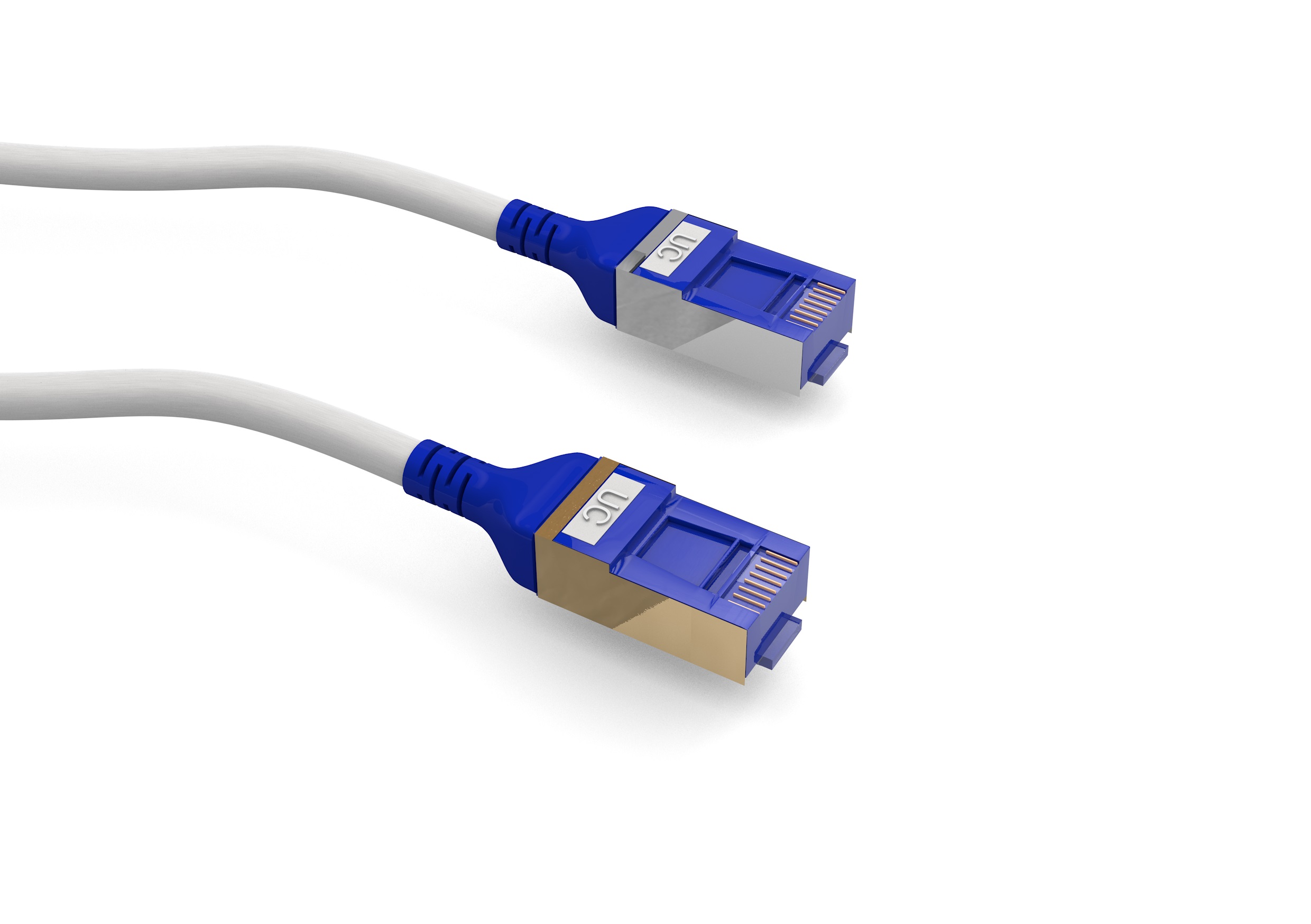
特雷卡推出SlimFlex节省空间Cat6a铜接线电缆
阅读更多 >6:17 上午

Draka UC在CommunicAsia 2016 通信展完美收官!
阅读更多 >6:32 上午
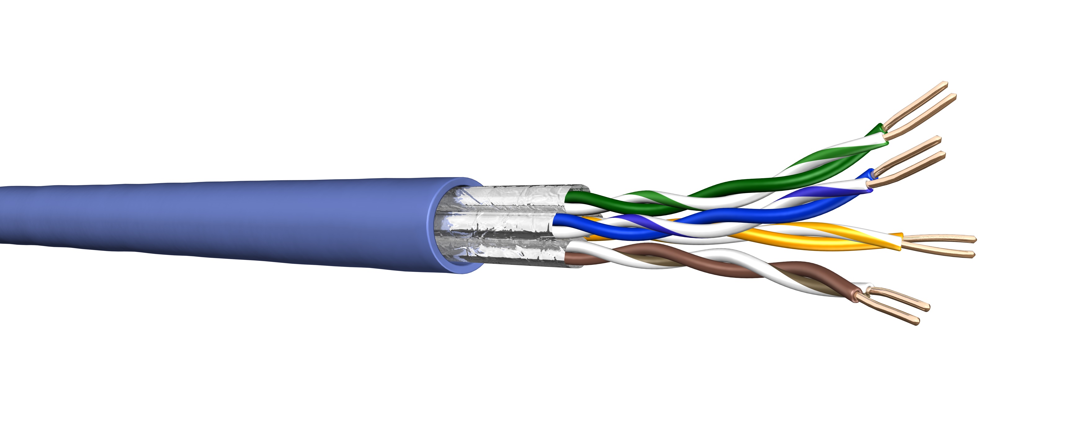
不遗余力
阅读更多 >7:44 上午
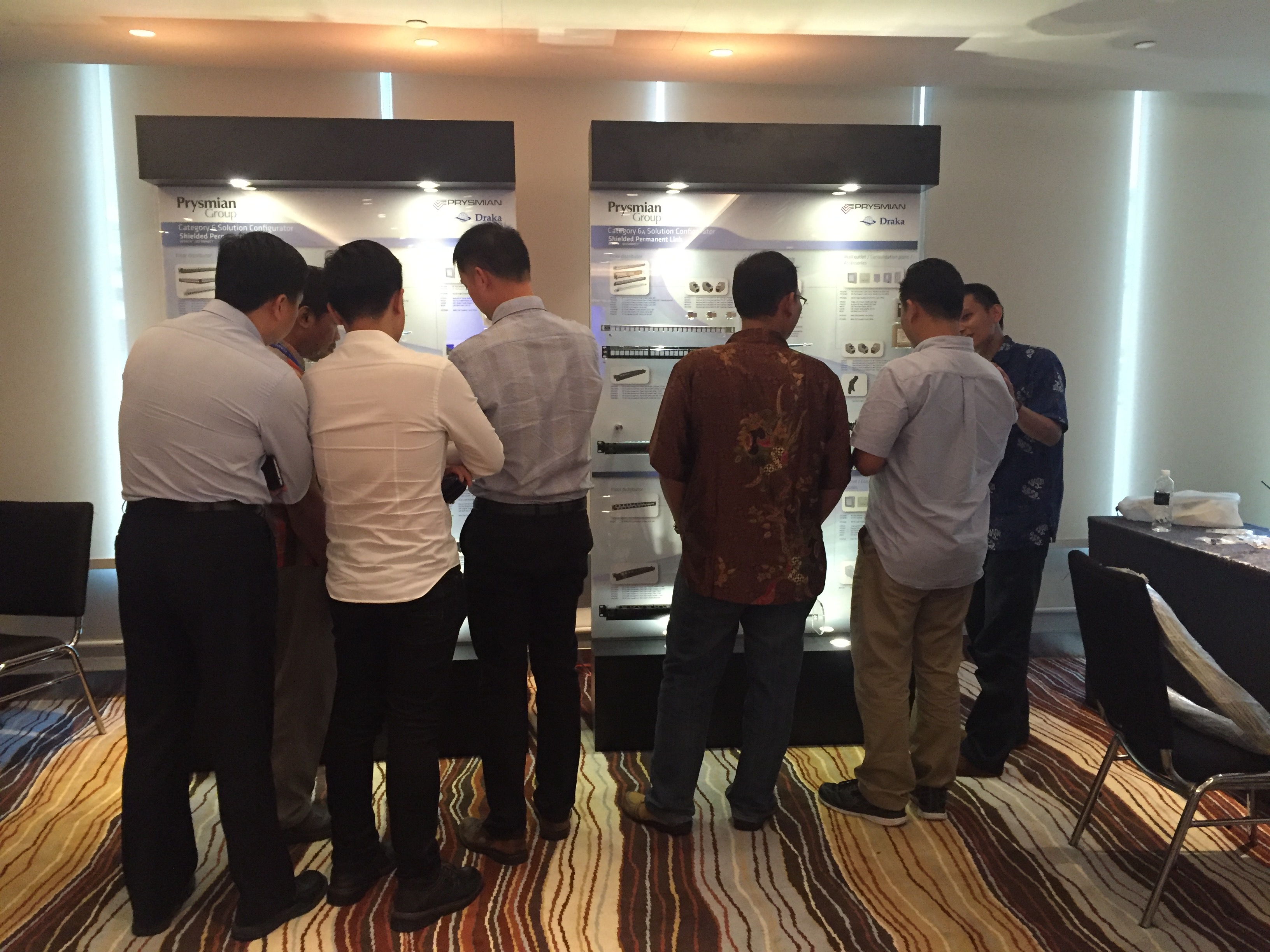
特雷卡研讨会在印度尼西亚雅加达举行
阅读更多 >5:00 下午

Cat 8 – 高速需求
阅读更多 >9:00 上午
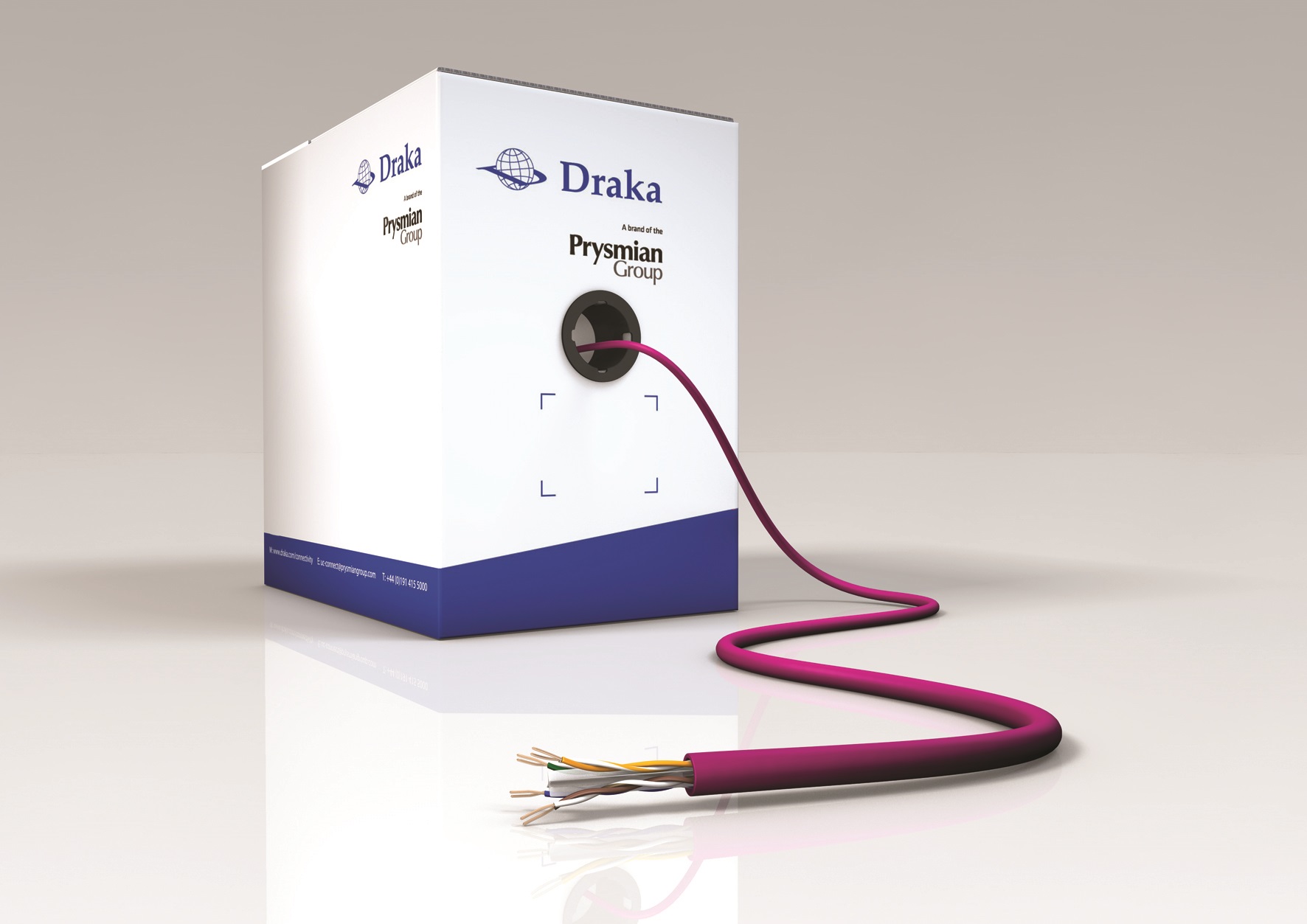
特雷卡创新提供高性能Cat.6 超纤数据缆
阅读更多 >3:00 下午

普睿司曼集团–网络联合研讨会
阅读更多 >1:32 上午

普睿司曼集团作为黄金赞助商全力赞助亚洲世界数据中心
阅读更多 >12:40 下午

普睿司曼集团在Fluke技术更新会话
阅读更多 >
